FENNEC
Every Link in the Chain: Inside a Living Safety Case
A safety case is built from linked artifacts, from hazard and risk assessment through verification and validation. This piece looks at each link, why the connections between them carry the argument, and how impact analysis follows those connections when a component changes.
Every Link in the Chain: Inside a Living Safety Case
The first and second pieces in this series looked at the safety case over time: how it carries forward after certification, and how evidence keeps flowing back into it. To see why that flow depends on connections, it helps to look inside the safety case itself.
A safety case is an evidence-based argument that an autonomous system is acceptably safe in a specific application.
Start with the application
Safety is assessed in the context of an application, not a product alone. “Collaborative” describes how a robot is used, not the robot itself. A typical industrial robot can work in a collaborative application, for example by using speed and separation monitoring. The American National Standards Institute (ANSI) safety standard for industrial robots, R15.06, allows for exactly this. Whether a particular setup is safe depends on the task, the payload, the speeds involved, and who is nearby. The same robot may call for different safety measures in two distinct working environments.
So the safety case has to capture that application in detail: what could go wrong in this defined setting, what will be done to mitigate it, and how that mitigation is traced through the entire safety case. That traceable line runs along a chain of linked artifacts, each one connected to the next.
The links in the chain
Most safety cases, whatever tools hold them, are built from the same core links.
Hazard and risk assessment. Identifying what could cause harm within the intended use and reasonably foreseeable misuse, and estimating how severe and how likely that harm would be.
Risk reduction measures and safety targets. What will be done about each risk, and how much risk reduction each measure must deliver, known as its safety target. Some measures are carried out by electrical, electronic, or programmable electronic (E/E/PE) safety systems, such as an obstacle detection system. Others are not: guarding, procedures, training, and information for the people who use the system.
Safety functions. Each E/E/PE measure becomes a defined safety function, such as a protective stop or speed and separation monitoring. The function inherits its safety target, expressed as a Performance Level (PL) under ISO 13849 or a Safety Integrity Level (SIL) under IEC 61508.
Safety requirements. What each function must do, how quickly, and how reliably, stated precisely enough to verify.
Hardware and software elements. The subsystems and components that carry out each function, along with their failure modes, diagnostics, and architecture. Reliability analysis of these elements shows whether each function can achieve its safety target.
Verification and validation. Test cases and their executions, providing evidence that each requirement is met and that each function performs as intended in the application.
The connections carry the argument
Each link on its own is an artifact. The argument lives in the connections between them, which is why traceability is an imperative.
Checking those connections is what the standards call verification: confirming that each lifecycle phase meets the expectations set by the one before it. The risk reduction measures answer to the hazard and risk assessment, the safety requirements answer to the safety functions, and the test cases answer to the requirements.
That is why assessors and testing laboratories look closely at the chain itself. Is every hazard tied to an assessed risk? Is every risk addressed by a measure with a safety target? Is every E/E/PE measure realized as a safety function that carries that target? Does the reliability analysis show each function can meet it? Is every requirement traced to a test, and every test to a result? Anything left unconnected is a gap in the argument, even if every individual artifact is well written.
Validation closes the loop from the other end. It confirms that the test cases, as executed, demonstrate that the system meets its Safety Requirements Specification (SRS).
The questions above get asked by the assessor during the certification process, usually artifact by artifact as each deliverable is reviewed. However, in a living safety case they stay useful long after the assessor leaves. When the robot moves to a new environment two years later, or a component is replaced, the team faces the same questions again, because they are the questions every change raises.
Impact analysis: following a change through the chain
The traceability this chain provides earns its keep when something changes. Before a modification is made, IEC 61508 calls for an impact analysis: a structured look at how the change affects functional safety and what has to be done as a result. The chain is what that analysis follows.
Consider a hardware change. A team replaces a safety-rated laser scanner with a newer, pre-certified model that has a slightly different response time (see Fig. 1).
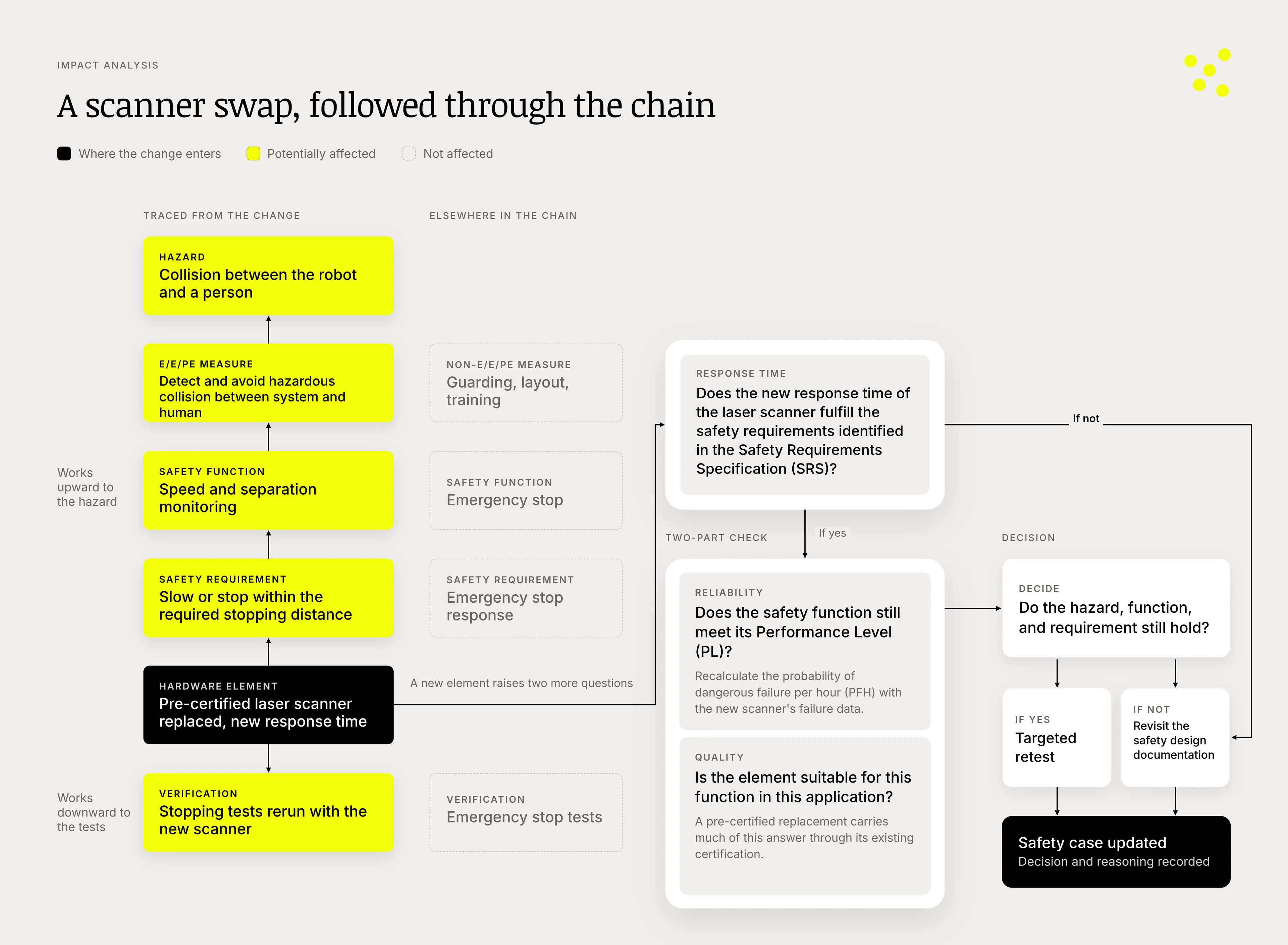
Impact analysis of a laser scanner replacement. The change enters at the element and is traced upstream to the hazard and downstream to the tests, while a two-part check confirms reliability (random hardware failures) and quality (systematic failures) before the decision is recorded.
The impact analysis starts at the element level, where the change enters the chain, and works upstream first. The scanner supports a speed and separation monitoring function, and that function carries a requirement: how quickly the robot must slow or stop when a person comes within a given distance. The requirement exists to address a potential hazard, a collision between the robot and a person. Even a small difference in the scanner’s response time can change the stopping distance the requirement depends on.
So the first check is direct: does the new scanner’s response time still satisfy the SRS? If it does not, the team returns to the safety design documentation before going any further.
The analysis then works downstream. The tests that verified the stopping behavior run again with the new scanner, and their results become new evidence in the safety case.
Working in both directions gives the team two views at once: bottom-up from the element that changed, and top-down from the hazard it protects against.
A replacement element also raises two questions the original design already answered, and they map to the two kinds of failure functional safety is built to manage. Reliability addresses random hardware failures: does the new scanner’s failure data still support the function’s PL or SIL once the probability of dangerous failure per hour (PFH) is recalculated? Quality addresses systematic failures: was the element designed and built with the rigor this function requires?
Because the replacement in this example is pre-certified, its certification already answers the quality question. A sensor that is not safety-rated is a different matter. The team would need to show assessors that it matches the quality of a certified element, including characterization under IEC 61496, which is substantial work and a topic for a future article.
The analysis ends in a decision, and a record of that decision. If the hazard analysis, function, and requirement still hold, and the new scanner meets its response time and reliability targets, the change calls for a targeted retest. If the new response time or failure data undermines the requirement, the team may need to revisit the safety design itself. Either way, the reasoning is documented, and the safety case stays current.
The previous piece in this series introduced the O-model. Here is a more detailed view of it, with impact analysis at its center (see Fig. 2 below). Picture the O as a wheel, with the impact analysis as its hub and spokes running out to the phases of the lifecycle. Events enter from outside the loop and from inside it: a supplier or component change, like the scanner example; the team’s own change, such as a software update or a retrained model; a newly exploited vulnerability; a revised standard or regulation; a change to the operating domain; or a field incident during operation. For each one, the analysis asks how far back the change must go. A new hazard sends the work back to hazard and risk assessment. A changed requirement goes back to the safety requirements. A change that leaves the requirements intact may only need re-verification. And when a field event calls for it, there is a fast path: immediate containment, such as restricting or disabling a function, while the full loop delivers the long-term fix.
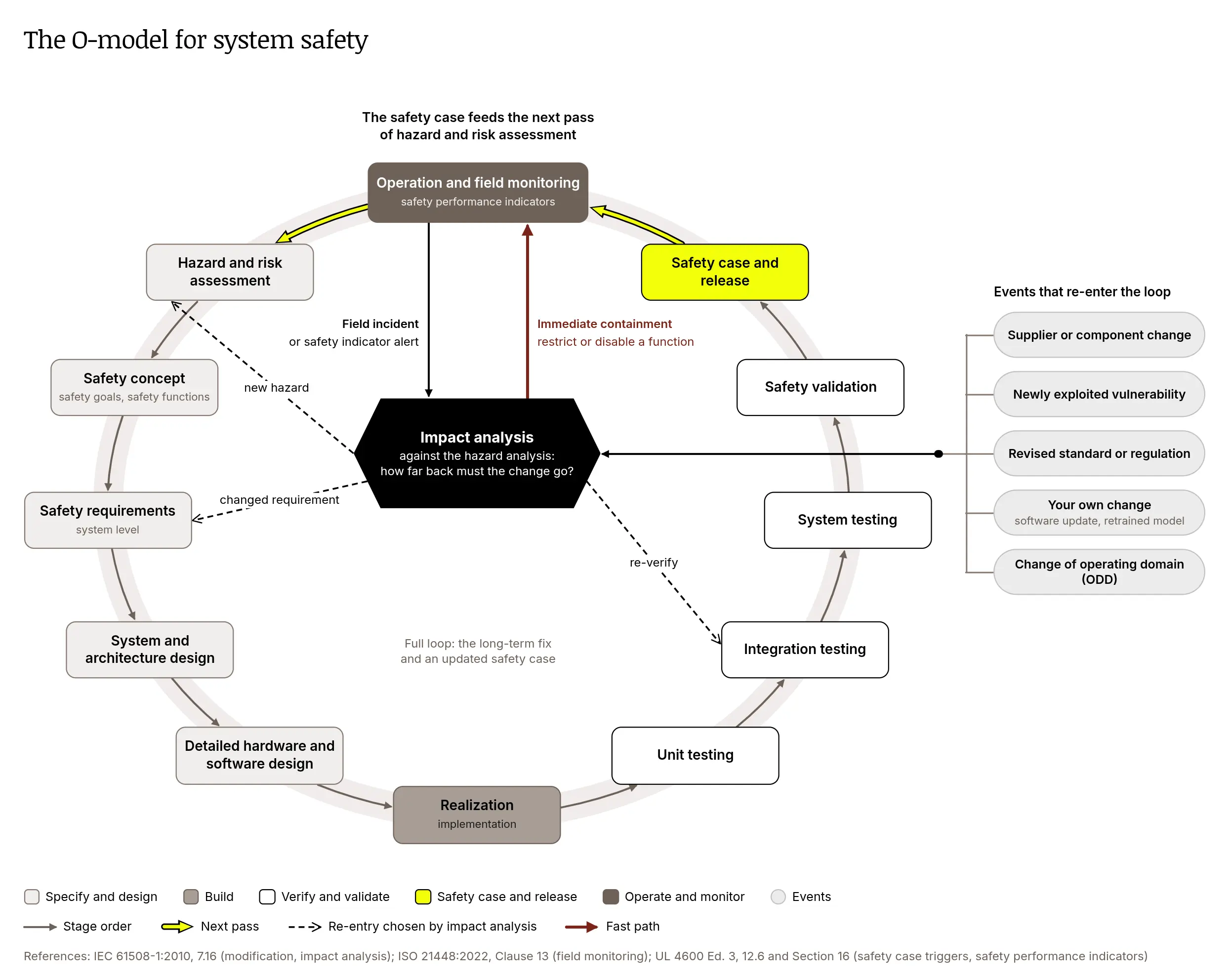
The O-model for system safety. Events re-enter the loop through the impact analysis, which determines how far back each change must go.
A change rarely needs to travel the whole loop. It needs to reach the right phase.
When the links are intact, an impact analysis can follow them rather than reconstruct them. That is the practical payoff of a connected safety case: a change becomes a question the team can answer with confidence.
Every link matters
A safety case is only as strong as its weakest connection. A careful hazard analysis does little if it never reaches the requirements, and a thorough test campaign proves little if no one can say which requirement it verifies.
Keeping every link connected is what lets a safety case keep learning.
Next in this series: where safety lives inside an organization, and what a folder structure can reveal about it.
Fennec Engineering is a team of functional safety engineers who build software. The ASAP Platform keeps every link in the safety case connected, and its built-in impact analysis shows how a proposed change propagates through the safety case: the hazards, safety functions, requirements, and tests it touches.